-

Vishay Intertechnology, Inc. announced that it is implementing restructuring actions designed to optimize the Company’s manufacturing footprint and streamline business decision making as it executes its Vishay 3.0 growth strategy.
The restructuring actions will be implemented in phases and include:
- Selling, general, and administrative functions will be streamlined beginning immediately and through 4Q 2025, resulting in severance payments to approximately 170 employees, or 6% of the SG&A workforce.
- The closure of three manufacturing facilities. A Diodes segment back-end facility in Shanghai, China is expected to be closed by the end of 2026 with production transfers completed in phases beginning 4Q 2025. In addition, two small facilities in the Resistors segment in Fichtelberg, Germany, and in Milwaukee, Wisconsin, are expected to be closed in 2026. As a result of these facility closures, Vishay will reduce its direct labor by approximately 365 employees, or 2% of its total manufacturing labor workforce.
- Various changes in manufacturing operations and production transfers, which will result in severance payments to approximately 260 employees.
The Company expects to incur pre-tax cash charges of approximately $38 to $42 million, primarily related to severance costs, as a result of these programs, mostly in 3Q 2024. Once the program is fully implemented by the end of 2026, Vishay expects to realize annualized cost savings of at least $23 million of which approximately $12 million is expected to be in selling, general and administration expenses. The Company expects to realize immediate annualized cost savings of approximately $9 million. Beginning 1Q 2025, the Company expects to realize approximately $12 million in annualized cost savings.
“As we implement Vishay 3.0, reshaping the Company and preparing for our next phase of growth, we continuously task ourselves with identifying opportunities to best foster a business minded approach to decision making, further enhance our customer first focus and improve cost efficiencies,” said Joel Smejkal, Vishay’s President and Chief Executive Officer.
“With that in mind, we are undertaking these restructuring actions in part to eliminate barriers to execution and to intensify the sense of urgency. We’re also taking our first step to optimize our global manufacturing footprint, closing smaller single product line facilities and moving toward campus manufacturing structures with multiple product lines. Collectively, these actions will help us execute our five-year growth strategy to accelerate our revenue growth rate, expand profitability and drive higher returns.”
The Company’s estimates of the costs related to its cost reduction programs and anticipated annual savings represent its current best estimates. However, such estimates are preliminary and subject to change as the Company implements these programs.
Original – Vishay Intertechnology
-

Vishay Intertechnology, Inc. announced results for the fiscal second quarter ended June 29, 2024.
Highlights
- 2Q 2024 revenues of $741.2 million
- Gross margin was 22.0% and included the negative impact of approximately 170 basis points related to the addition of Newport
- EPS of $0.17
- 2Q 2024 book-to-bill of 0.86 with book-to-bill of 0.82 for semiconductors and 0.90 for passive components
- Backlog at quarter end was 4.6 months
“During the second quarter, we executed well on our Vishay 3.0 strategic plan, deepening our customer engagements supported by capacity that has landed and that we will continue to expand, and advancing our silicon carbide strategy as we prepare for the megatrends in sustainability and e-mobility,” said Joel Smejkal, President and CEO.
“Revenue, including a full quarter of Newport, was flat quarter over quarter, primarily reflecting schedule agreement adjustments by automotive Tier 1 customers. At mid-year 2024, it is apparent that the industry recovery is taking longer than we had expected at the beginning of the year. As a result, we are adjusting the timetable of the Itzehoe, Germany expansion project beyond 2024 while holding to our planned capital investment of $2.6 billion between 2023 and 2028. For 2024, we now plan to invest between $360 million to $390 million in capex.”
3Q 2024 Outlook
For the third quarter of 2024, management expects revenues in the range of $745 million +/- $20 million, with gross profit margin in the range of 21.0% +/- 50 basis points, including the negative impact of approximately 175 to 200 basis points from the addition of Newport.Original – Vishay Intertechnology
-
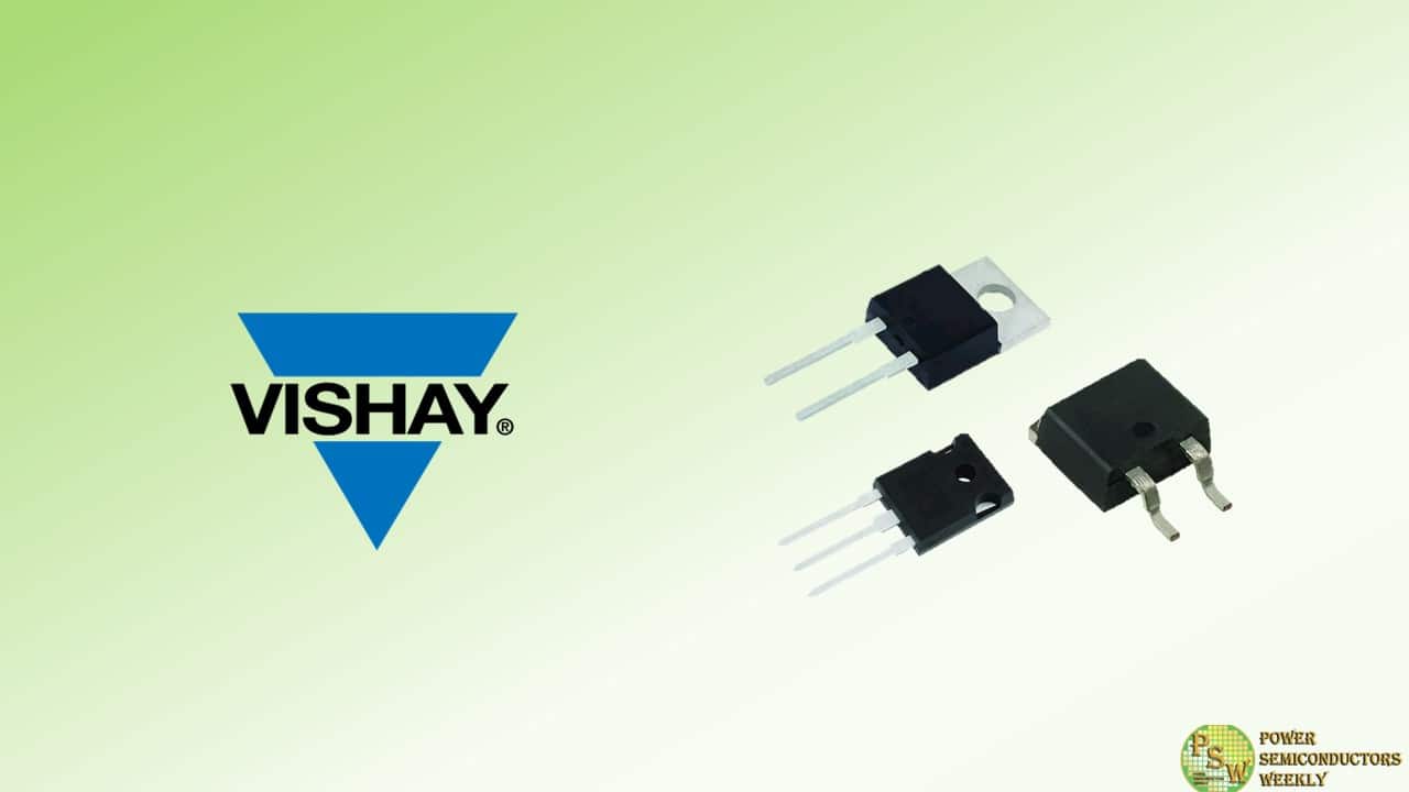
Vishay Intertechnology, Inc. introduced 16 new Gen 3 1200 V silicon carbide (SiC) Schottky diodes. Featuring a merged PIN Schottky (MPS) design, the Vishay Semiconductors devices combine high surge current robustness with low forward voltage drop, capacitive charge, and reverse leakage current to increase efficiency and reliability in switching power designs.
The next-generation SiC diodes released today consist of 5 A to 40 A devices in the TO-220AC 2L, TO-247AD 2L, and TO-247AD 3L through-hole and D2PAK 2L (TO-263AB 2L) surface-mount packages. The diodes offer a low capacitance charge down to 28 nC, while their MPS structure — which features a backside thinned via laser annealing technology — delivers a reduced forward voltage drop of 1.35 V. In addition, the devices’ low typical reverse leakage current down to 2.5 µA at 25 °C reduces conduction losses, ensuring high system efficiency during light loads and idling. Unlike ultrafast diodes, the Gen 3 devices have virtually no recovery tail, which further improves efficiency.
Typical applications for the diodes will include AC/DC PFC and DC/DC ultra high frequency output rectification in FBPS and LLC converters for solar power inverters; energy storage systems; industrial drives and tools; and datacenters. For the harsh environments of these applications, the devices combine operating temperatures to +175 °C with forward surge ratings to 260 A for high robustness. In addition, diodes in the D2PAK 2L package feature a molding compound with a high CTI ≥ 600, ensuring excellent electrical insultation at elevated voltages.
Offering high reliability, the RoHS-compliant and halogen-free devices have passed higher temperature reverse bias (HTRB) testing of 2000 hours and temperature cycling testing of 2000 thermal cycles.
Device Specification Table:
Part # IF(AV) (A) IFSM (A) VF at IF (V) QC (nC) Configuration Package VS-3C05ET12T-M3 5 42 1.35 28 Single TO-220AC 2L VS-3C10ET12T-M3 10 84 1.35 55 Single TO-220AC 2L VS-3C15ET12T-M3 15 110 1.35 81 Single TO-220AC 2L VS-3C20ET12T-M3 20 180 1.35 107 Single TO-220AC 2L VS-3C05ET12S2L-M3 5 42 1.35 28 Single D2PAK 2L VS-3C10ET12S2L-M3 10 84 1.35 55 Single D2PAK 2L VS-3C15ET12S2L-M3 15 110 1.35 81 Single D2PAK 2L VS-3C20ET12S2L-M3 20 180 1.35 107 Single D2PAK 2L VS-3C10EP12L-M3 10 84 1.35 55 Single TO-247AD 2L VS-3C15EP12L-M3 15 110 1.35 81 Single TO-247AD 2L VS-3C20EP12L-M3 20 180 1.35 107 Single TO-247AD 2L VS-3C30EP12L-M3 30 260 1.35 182 Single TO-247AD 2L VS-3C10CP12L-M3 2 x 5 42 1.35 28 Common cathode TO-247AD 3L VS-3C20CP12L-M3 2 x 10 84 1.35 55 Common cathode TO-247AD 3L VS-3C30CP12L-M3 2 x 15 110 1.35 81 Common cathode TO-247AD 3L VS-3C40CP12L-M3 2 x 20 180 1.35 107 Common cathode TO-247AD 3L Samples and production quantities of the new SiC diodes are available now, with lead times of 13 weeks.
Original – Vishay Intertechnology
-

Vishay Intertechnology, Inc. announced that at PCIM Europe 2024 the company will be showcasing its broad portfolio of power management solutions that address several increasingly important trends in power electronics, including e-mobility, high efficiency power conversion, energy storage, and grid management. In Hall 9, Booth 208, Vishay experts will be available to discuss the company’s extensive offering of passive and semiconductor solutions for these next-generation applications.
Taking center stage for Vishay at PCIM will be the company’s newly released 1200 V MaxSiC™ series silicon carbide (SiC) MOSFETs, which deliver on-resistances of 55 mW, 95 mW, and 280 mΩ in standard packages for industrial applications, with custom products also available.
In addition, Vishay will provide a roadmap for 650 V to 1700 V SiC MOSFETs with on-resistances ranging from 10 mΩ to 1 Ω. Vishay’s SiC platform is based on proprietary MOSFET technology — enabled through the company’s acquisition of MaxPower Semiconductor, Inc. — which will address market demands in traction inverter, photovoltaic energy conversion and storage, on-board charger, and charging station applications. At the booth, Vishay’s experts will also be discussing upcoming planned releases of the MaxSiC platform, including AEC-Q101 Automotive Grade products.
At PCIM, Vishay will be offering a variety of application-focused demonstrations, including:
- A high voltage intelligent battery shunt for 400 V and 800 V batteries
- A 40 kW resettable electronic fuse (eFuse) for 400 V and 800 V battery electric vehicles (BEV)
- A unidirectional, 11 kW three-phase AC on-board charger (OBC) with a BOM consisting of 90 % Vishay parts
- A bidirectional 10 kW eFuse for 48 V applicationsA collaborative robot workstation featuring Vishay power resistors, ESTA power electronic capacitors (PEC), Automotive Grade diodes, SiC MOSFETs, and an SiC-based auxiliary power converter.
Vishay passive components on display at PCIM will include IHPT series solenoid-based haptic actuators featuring Immersion Corporation licenses, a 5.5 kW transformer / inductor for LLC applications, and IHLE® series low profile, high current inductors with integrated e-field shields; wirewound resistors and charging resistors featuring hybrid wirewound technology; thick film power resistors; robust metallized polypropylene film capacitors, including AC and pulse capacitors and DC-Link capacitors with high temperature operation up to +125 °C and the ability to withstand temperature humidity bias (THB) testing of 85 °C / 85 % for 1000 h; X1, X2, and Y2 EMI suppression film capacitors certified to safety and humidity robustness grade IIIB; and DC and AC power electronic capacitors (PEC) with high impulse current ratings, low inductance, and high reliability.
Highlighted Vishay semiconductor solutions will consist of surface-mount diodes in the eSMP® and FlatPAK 5×6 packages; leadless surface-mount diodes in the DFN, CLP, and LLP series packages; and 650 V and 1200 V SiC Schottky diodes up to 20 A in eSMP® series and 40 A in power packages for AC/DC power factor correction (PFC) and ultra high frequency output rectification. In addition, Vishay will be showcasing microBUCK® and microBRICK® buck regulators, including the 60 V input SiC967 synchronous buck regulator with integrated power MOSFETs and inductors; high voltage MOSFETs in the PowerPAK 10×12 package; automotive power modules in the EMIPAK 1B, MaacPAK, FlatPAK, and HC0 packages; and industrial power modules in Gen III TO-244, IAP, SOT-227, and MTC packages.
Prior to the exhibition, on June 9, Vishay’s Sanjay Havanur — senior manager of system applications — will be presenting the seminar “Silicon Is Still Here: A Refresher on the Narrow Bandgap Power MOSFETs and Their Datasheets” at 2 p.m. in the Arvena Park Hotel. During the show, Claudio Damilano — director of product marketing and market development, power modules — will present “Evolution in Vishay Power Modules for E-Mobility: Solutions for High Voltage and Low Voltage Applications” on June 11, at 3:50 p.m. in Hall 6, Booth 220.
Original – Vishay Intertechnology
-
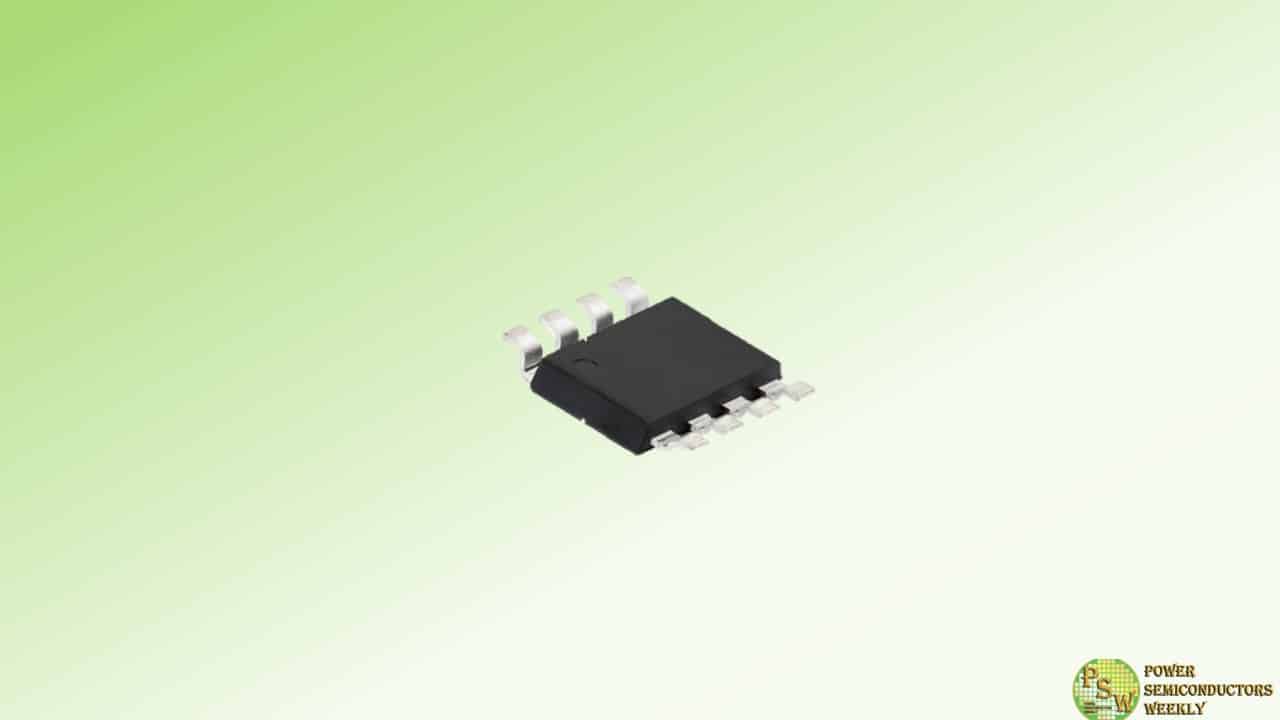
To provide higher efficiency and power density for telecom, industrial, and computing applications, Vishay Intertechnology, Inc. introduced its first fourth-generation 600 V E Series power MOSFET in the new PowerPAK® 8 x 8LR package.
Compared to previous-generation devices, the Vishay Siliconix n-channel SiHR080N60E slashes on-resistance by 27 % and resistance times gate charge, a key figure of merit (FOM) for 600 V MOSFETs used in power conversion applications, by 60 % while providing higher current in a smaller footprint than devices in the D²PAK package.
Vishay offers a broad line of MOSFET technologies that support all stages of the power conversion process, from high voltage inputs to the low voltage outputs required to power the latest high tech equipment. With the SiHR080N60E and other devices in the fourth-generation 600 V E Series family, the company is addressing the need for efficiency and power density improvements in two of the first stages of the power system architecture — power factor correction (PFC) and subsequent DC/DC converter blocks.
Typical applications will include servers, edge computing, super computers, and data storage; UPS; high intensity discharge (HID) lamps and fluorescent ballast lighting; telecom SMPS; solar inverters; welding equipment; induction heating; motor drives; and battery chargers.
Measuring 10.42 mm by 8 mm by 1.65 mm, the SiHR080N60E’s compact PowerPAK 8 x 8LR package features a 50.8 % smaller footprint than the D²PAK while offering a 66 % lower height. Due to its top-side cooling, the package delivers excellent thermal capability, with an extremely low junction to case (drain) thermal resistance of 0.25 °C/W.
This allows for 46 % higher current than the D²PAK at the same on-resistance level, enabling dramatically higher power density. In addition, the package’s gullwing leads provide excellent temperature cycle capability.
Built on Vishay’s latest energy-efficient E Series superjunction technology, the SiHR080N60E features low typical on-resistance of 0.074 Ω at 10 V and ultra low gate charge down to 42 nC. The resulting FOM is an industry-low 3.1 Ω*nC, which translates into reduced conduction and switching losses to save energy and increase efficiency in power systems > 2 kW.
For improved switching performance in hard-switched topologies such as PFC, half-bridge, and two-switch forward designs, the MOSFET released today provides low typical effective output capacitances Co(er) and Co(tr) of 79 pF and 499 pF, respectively. The package also provides a Kelvin connection for improved switching efficiency.
The device is RoHS-compliant and halogen-free, and it is designed to withstand overvoltage transients in avalanche mode with guaranteed limits through 100 % UIS testing.
Original – Vishay Intertechnology
-

Vishay Intertechnology, Inc. issued the following statement from its Board of Directors in response to the press release issued on April 22, 2024 by Mountaineer Partners Management, LLC (“Mountaineer”) in which Mountaineer published its letter to the Board of Directors urging the Board to consider adopting and implementing a $600 million accelerated share repurchase.
Vishay regularly engages with our stockholders and welcomes constructive input focused on enhancing value. Vishay’s CEO has held numerous discussions with Mountaineer since his appointment to the position on January 1, 2023, and the senior management team met with stockholders most recently at the company’s Investor Day held on April 2, 2024.
Vishay’s Board appreciates and is carefully evaluating the suggestion made by Mountaineer along with input from other stockholders to determine the course of action that is in the best interest of the company and all stockholders.
Original – Vishay Intertechnology
-
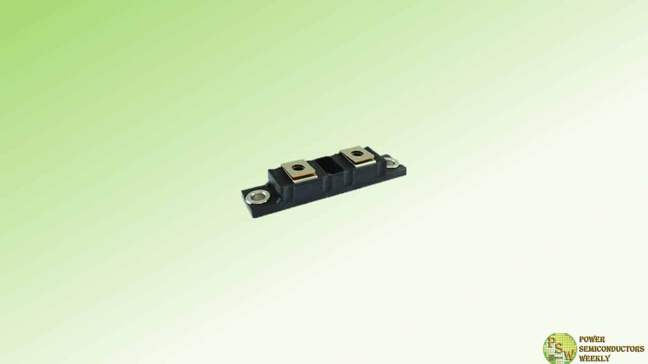
Vishay Intertechnology, Inc. introduced two new FRED Pt® 500 A Ultrafast soft recovery diode modules in the new TO-244 Gen III package. Offering higher reliability than previous-generation solutions, the Vishay Semiconductors VS-VSUD505CW60 and VS-VSUD510CW60 are designed to reduce losses and EMI / RFI in high frequency power conditioning systems.
The rugged TO-244 package of the diode modules released today withstands 46 000 IOL cycles at given conditions, offering an improved life expectancy over previous-generation devices. In addition, the industry-standard package is footprint-compatible with competing solutions in the TO-244 to provide a drop-in replacement for existing designs.
The VSUD505CW60 and VS-VSUD510CW60 are ideally suited for high frequency welding; high current converters and ballast water management systems (BWMS) in railway equipment, cranes, and ships; UPS; and other applications where switching losses comprise a significant portion of the total losses. In these applications, the softness of their recovery eliminates the need for a snubber, reducing component counts and lowering costs.
Offered in a common cathode configuration, the diode modules provide low forward voltage drop down to 0.82 V, thermal resistance — junction to case — of 0.16 °C/W, and an operating temperature range up to +175 °C.
Device Specification Table:
Part number VS-VSUD505CW60 VS-VSUD510CW60 VR (V) 600 IF(AV) (A) 500 Qrr typical (nC) 460 1770 trr (ns) 178 270 VFM @ 250 A, +175 °C (V) 0.95 0.82 RthJC per diode (°C/W) 0.160 Package TO-244 Samples and production quantities of the new FRED Pt® soft recovery diode modules are available now, with lead times of 26 weeks.
Original – Vishay Intertechnology
-

The Specialty Thin Film (STF) division of Vishay Intertechnology, Inc. announced that its Electro-Films (EFI) factory in Warwick, Rhode Island, has been certified to the IATF 16949:2016 quality standard for the IGBR family of back contact wirebondable gate resistors, designed to reduce noise in silicon carbide (SiC) MOSFET power modules.
Based on ISO 9001:2015 — with additional automotive customer-specific requirements — IATF 16949:2016 is the global technical specification and quality management standard for the automotive industry. With this certification, the quality management system at the EFI Warwick factory is now certified to ISO 9001:2015 for all products, and IATF 16949:2016 for IGBR resistors. In addition, its environmental management system is certified to ISO 14001:2015 and ISO 45001:2018.
Original – Vishay Intertechnology
-
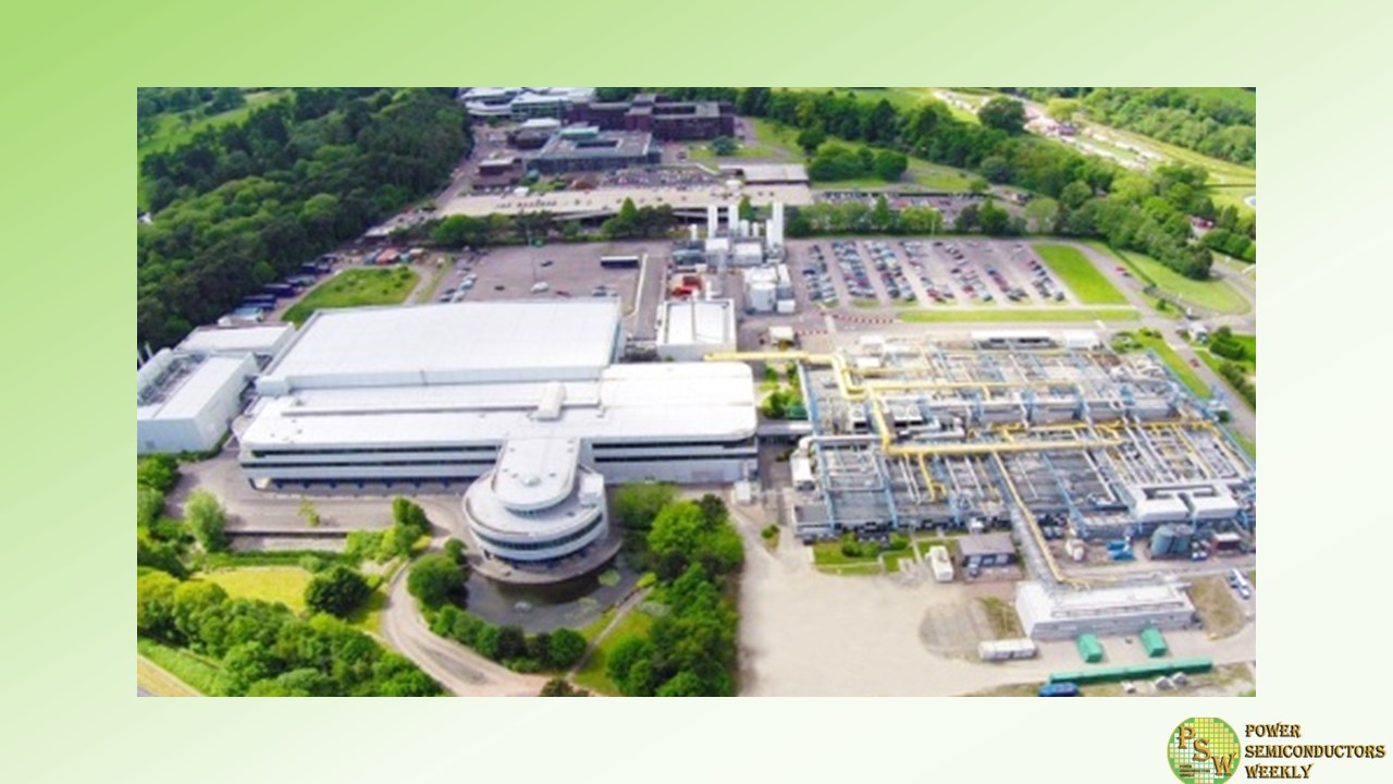
Vishay Intertechnology, Inc. and Nexperia B.V. announced in November 2023 that they had entered into an agreement that Vishay will acquire Nexperia’s wafer fabrication facility and operations located in Newport, South Wales, U.K.
At the time of that announcement, the closing of Newport wafer fab transaction was subject to UK government review, the purchase rights of a third party, and customary closing conditions. Nexperia is pleased to announce that all conditions to the sale have now been met and the sale of Newport wafer fab to Vishay is now finalised, today, 6th March, securing a future for its employees and for the site.
Original – Nexperia
-
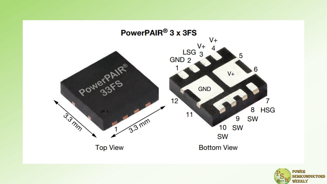
Vishay Intertechnology, Inc. introduced a new 80 V symmetric dual n-channel power MOSFET that combines high and low side TrenchFET® Gen IV MOSFETs in a single 3.3 mm by 3.3 mm PowerPAIR® 3x3FS package. For power conversion in industrial and telecom applications, the Vishay Siliconix SiZF4800LDT increases power density and efficiency, while enhancing thermal performance, reducing component counts, and simplifying designs.
This dual MOSFET can be used in place of two discrete devices typically specified in the PowerPAK 1212 package — saving 50 % board space. The device provides designers with a space-saving solution for synchronous buck converters, point of load (POL) converters, and half- and full-bridge power stages for DC/DC converters in radio base stations, industrial motor drives, welding equipment, and power tools. In these applications, the high and low side MOSFETs of the SiZF4800LDT form an optimized combination for 50 % duty cycles, while its logic level turn-on at 4.5 V simplifies circuit driving.
To increase power density, the MOSFET offers best in class on-resistance down to 18.5 mW typical at 4.5 V. This is 16 % lower than the closest competing device in the same package dimensions. For increased efficiency in high frequency switching applications, the SiZF4800LDT offers a low on-resistance times gate charge — a key figure of merit (FOM) for MOSFETs used in power conversion applications — of 131mW*nC and on-resistance times gain-drain charge
The device’s flip-chip technology enhances thermal dissipation — resulting in 54 % lower thermal resistance compared to competing MOSFETs. The SiZF4800LDT’s combination of low on-resistance and thermal resistance results in a continuous drain current of 36 A, which is 38 % higher than the closest competing device. The MOSFET features a unique pin configuration that enables a simplified PCB layout and supports shortened switching loops to minimize parasitic inductance. The SiZF4800LDT is 100 % Rg- and UIS-tested, RoHS-compliant, and halogen-free.
Competitor Comparison Table:
Part number SiZF4800LDT (New) Competitor SiZF4800LDTPerformance improved Package PowerPAIR 3x3FS PowerPAIR 3x3FS Dimensions (mm) 3.3 x 3.3 x 0.75 3.3 x 3.3 x 0.75 – Configuration Symmetric dual Symmetric dual – VDS (V) 80 80 – VGS (V) ± 20 ± 20 – RDS(on) (mΩ) @ 4.5 VGS Typ. 18.5 22 +16 % Max. 23.8 29 +18 % Qg (nC) @ 4.5 VGS Typ. 7.1 6.0 – FOM – 131 132 +1 % ID (A) Max. 36 26 +38 % RthJC (C/W) Max. 2.2 4.8 +54 % Original – Vishay Intertechnology
